Application notes
WiFi on Highways
The PAT2450G13XP is a dual-band (S-band + C-band), dual polarization (+/-45o) panel antenna, adapted both for indoor and outdoor applications in the ISM band including IEEE 802.11ac, b, g, n and Bluetooth. Designed for operating under severe weather conditions.

High quality construction of pole mounting elements guarantee easy elevation and easy tilt down as well as rock-stable operation. It can be used as customer premise equipment and as small base stations.
An example of using this antenna in a WiFi deployment on highways is presented. Each 500m a base station is placed. Each base station contains 2 antennas, covering both directions of the Highway. A metallic fence separates both ways of the highway.

Incident Field

Total Field

Second simulation
A second simulation of the incident and total field is performed with a cargo truck obstructing the link


Circular Polarized Antennas
Advantages of circular polarized (CP) antennas
In ITELITE we have designed many CP antennas for GPS and Glonass customized applications. Now we are introducing to our stock the PAT5019CP antenna. This is a panel antenna, with 18 dBi gain for both for indoor and outdoor applications in the ISM band including IEEE 802.11ac. It can be configured for Right Hand Circular Polarization (RHCP) or Left Hand Circular Polarization (LHCP).

The first advantage has to do with the Faraday Effect. As signals travel through the atmosphere they become de-polarized, causing undesirable reception of the opposing polarity. This effect is more severe at lower frequencies, such as C-Band, and affects all linear polarized signals. CP signals are immune to this affect, allowing lo improve the link’s performance while eliminate problems related with polarization mismatch and cross polarization discrimination.

Third, easier installation. With linear polarized antennas, the risk of being misaligned is constant. When that happened, the efficiency of the system decreases and more time would be needed for aligning the polarizations. As it was mentioned, the Faraday Effect could cause the misalignment, and also signal reflections. With CP signals that is not a problem, and the installation only requires ensuring that the antenna is aimed to the correct direction.
Applications such live video transmission need high link reliability. When the link is implemented in complex environments (with obstacles, for instance), or the transmitter or receiver is in constant motion, the CP antennas would highly contribute to ensure a reliable link. Live video streaming using a transmitter in constant motion, or FPV drones applications are good scenarios for using our CP antennas.


Horn Antennas
Dealing with Electromagnetic Interference (EMI)
Our Horn antennas are ideal where you need a very uniform and precise coverage. Also, they are suitable to use in harsh environments like a tight base stations with many aggressor signals spoiling your communication link. We provide a wide variety of models to suit your needs for different coverage. The HRN5008DPX-90, HRN5012DPX-45, HRN5015DPX-30 and HRN5018DPX-20 provides 90°, 45°, 30° and 20° respectively. In this application note we will describe the main features of our horn antennas and how do they perform in some scenarios.


Ports and feeding
A lot of the antennas offered in the market do not considerer close attention to the proper design of the feeding ports. Usually, for achieving a more compact size, the isolation between both ports is affected. Our design ensures more than 45 dB isolation between ports, what contributes to guarantee a solid and stable link, with lower bit-rate error.


By the other hand, our antennas do not have special ports that increase the cost of the antenna. In the end of the day, such special ports use inside coax cables and transitions to waveguide, that provides the same performance of a regular coax cable feeding method with proper pigtail.
Uniform and precise coverage
With our Horn antennas you would cover exactly the areas you want. Due to the very low sideloves and controlled radiation pattern, the coverage is uniform. The following example will compare the performance of a regular panel antenna with a horn antenna with similar gain and beam-width. Consider how one regular microstrip antenna (PRA5014XP) radiates. The plot below is the Electric field radiated from the antenna: significant amount of radiation leaks toward different directions, even backwards, resulting in potential interference with nearby equipments and odd coverage.

Placing this antenna on the top of a mast and simulating the electric field on a wide terrain, can give us a clear picture about how the coverage looks like. The plot below shows a top view of such scenario. At the bottom of the picture is placed our antenna on the top of the mast, with 30° down tilt. As we can see, the coverage is not uniform. There are some holes in the coverage area and we can also see the effect of the side loves.

Our horn antennas generate a radiation pattern with no side lobes, and direct the radiation evenly to the coverage area. The picture below shows the electric field generated by the HRN5015DPX-30 antenna. We can notice how well the electric field is propagating without generating side lobes.


Now, we can perform the same simulation, placing the antenna on the top of a mast, and checking the coverage on the terrain. The plot below shows a top view of the scenario. At the bottom of the picture is placed the horn antenna on a top of the mast, with 30° down tilt. The even coverage obtained with the horn antenna is desire in any deployment, where you want to selectively cover the terrain you want, just selecting the proper horn model from our stock.

The RF planning is simpler and the inter-site interference would be easy to avoid with the uniform and stable patter of our horn antennas. Not only the horn antenna is less susceptible to external interferences, but it would be easier to control the interference that you could generate to nearby receivers.
Electromagnetic Interference (EMI)
Ensuring Antenna Performance in complex wireless environments could be challenging. Usually the wireless service providers have to accommodate their systems in tight base stations with many aggressor signals around, causing severe electromagnetic interference. In the next example we will simulate the interference suffered by one of our antennas when it is installed in a base station with another 2 antennas. First, we will check the interference suffered by a regular panel antenna (PRA5014XP), and then we will compare the results using a compatible horn antenna (HRN5015DPX-30).
The base station has installed a 2.4GHz dipole antenna and a 3.5Ghz panel antenna (PAT3510XP). We will simulate how a 5GHz panel antenna (PRA5014XP) is affected while the 2 other antennas are transmitting. The 2.4Ghz dipole is connected to a WIFi 802.11n radio, the PAT3510XP antenna is connected to a WiMax 802.16 radio and finally the PRA5014XP is connected to a WiFi 802.11ac radio.

The following plot shows the simulation’s results when the 5GHz antenna is receiving, and the 2.4GHz and 3.5GHz antenna are transmitting. Each transmitter is considered as a potential source of EMI.
The matrix results shows with the red color that both ports of the PAT3510XP antenna are causing EMI to the PRA5014XP antenna. The problem is caused by out-band interference with the 2nd harmonic of the WiMax Radio. Altoug this problem could be mitigated by using a bandpass filter in the WiFi 802.11 ac radio, still.

By the other hand, the 3th harmonic of the WiFi 802.11n radio, with the 2.4GHz Dipole antenna it is also causing out-band interference to the PRA5014XP. The yellow color represents a potencial problem in the link.

Replacing the panel antenna for the HRN5015DPX-30, the scenario is much better. Now the antenna is not affected by the interference caused by the out-band harmonics interference, and the system is stable, thanks of the advantages of using the horn antenna HRN5015DPX-30.

Cambium
Successful Deployment with Cambium ePMP3000
ITELITE QOMD5013XP was used with Cambium ePMP3000 in Italy for improving the link performance in a noisy scenario. The result? The contractor answers: “We are impressed with link quality. Same frequency, same output power, same target RSL level for SMs, we reduced retransmissions and incremented modulation levels. All traffic is 64QAM for 802.11n SMs and 256QAM for 802.ac SMs, both in uplink and downlink”. The contractor also acknowledged that even though the AP was updated, “the antenna made the big difference”.
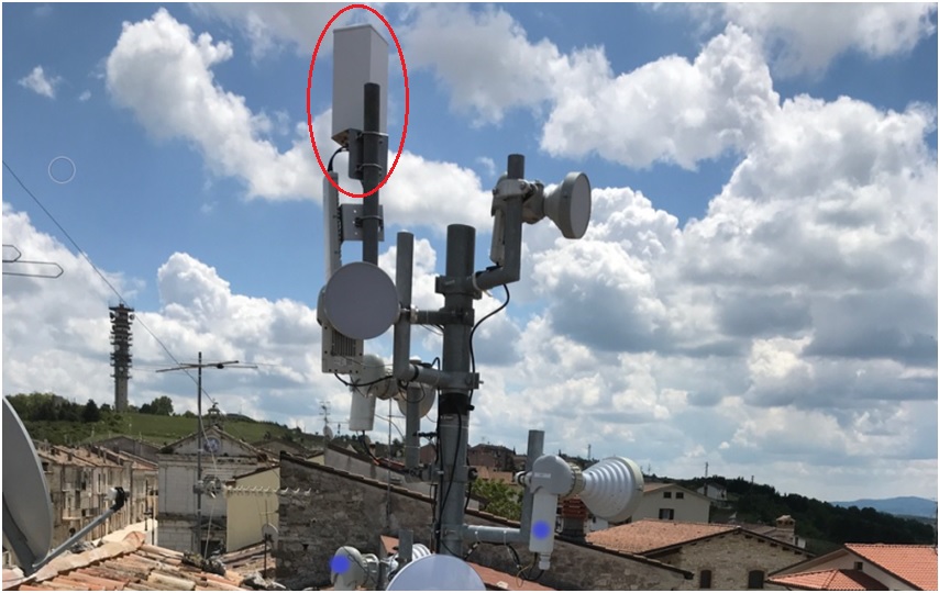
How does the QOMD5013XP antenna work? It provides coverage of 360° in the azimuth plane and 12° for the elevation plane via 4 overlapping sectors with all opposite sectors interconnected. The antenna gain is 13dBi and it covers the entire 5.1-5.9 GHz band. This antenna is suitable for 4×4 Multi-User MIMO (MU-MIMO) applications, grouping of SMs and limits the inter-sector interference.

